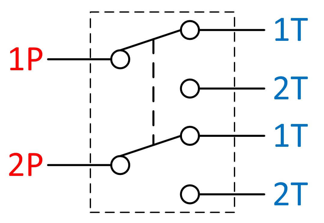
Dpdt Relay Pin Diagram. There are 2 inputs for dpdt with two outputs. In order to know how to connect a dpdt relay, you must. — 3.3 detailed wiring diagrams for common dpdt relay applications. the dpdt relay is often represented in schematic diagrams as two separate single pole double throw (spdt) relays connected together. — dpdt relay pin configuration. Here are simplified wiring diagrams for common dpdt relay. A typical dpdt relay wiring diagram includes the coil connections and the contact connections. dpdt relay wiring diagram. The default pin out of the dpdt relay varies. — the dpdt relay is an electromagnetic device used in electric motors. It is also called the double (d) pole (p) double (d) throw (t) relay. dpdt relay wiring diagram. Dpdt relay usually has eight pins. The dpdt relay comes with two coils terminals, two independent common c1 and c2, and 2 normally open, and 2 normally closed terminals. in this article, we go over how to connect a double pole double throw (dpdt) relay in a circuit.
from wiredataseedienstos.z4.web.core.windows.net
— the dpdt relay is an electromagnetic device used in electric motors. — electroschematics explores the dpdt relay (double pole double throw), common applications, and offers useful wiring diagrams. A typical dpdt relay wiring diagram includes the coil connections and the contact connections. dpdt relay wiring diagram. Dpdt relay usually has eight pins. This is the diagram below to learn all the pin terminals of a double pole double throw (dpdt). The default pin out of the dpdt relay varies. Here are simplified wiring diagrams for common dpdt relay. — dpdt relay pin configuration. The dpdt relay comes with two coils terminals, two independent common c1 and c2, and 2 normally open, and 2 normally closed terminals.
Working Of Spdt Switch
Dpdt Relay Pin Diagram This is the diagram below to learn all the pin terminals of a double pole double throw (dpdt). A typical dpdt relay wiring diagram includes the coil connections and the contact connections. Dpdt relay usually has eight pins. The dpdt relay comes with two coils terminals, two independent common c1 and c2, and 2 normally open, and 2 normally closed terminals. This is the diagram below to learn all the pin terminals of a double pole double throw (dpdt). — electroschematics explores the dpdt relay (double pole double throw), common applications, and offers useful wiring diagrams. In order to know how to connect a dpdt relay, you must. dpdt relay wiring diagram. the dpdt relay is often represented in schematic diagrams as two separate single pole double throw (spdt) relays connected together. Here are simplified wiring diagrams for common dpdt relay. There are 2 inputs for dpdt with two outputs. — 3.3 detailed wiring diagrams for common dpdt relay applications. in this article, we go over how to connect a double pole double throw (dpdt) relay in a circuit. The default pin out of the dpdt relay varies. — dpdt relay pin configuration. — the dpdt relay is an electromagnetic device used in electric motors.